
|
Product description |
Published: 02-06-2025 Print date: 27.06.2026 |
|
|
Product description |
Published: 02-06-2025 Print date: 27.06.2026 |
Promoting the flow in silos and cleaning the silo wallsFlow in a silo can be promoted with a hammer. But the use of pneumatic knockers is a much better way. This gives maximum impact, without damage.
APPLICATIONThe Pneumatic Knocker is used for bulk goods with flow problems, such as bridging, funnel flow and stagnant zones, when high speed shakers and vibrators with soft sine-shaped oscillations are no longer effective. Better than a hammerThe effect of the knocker is comparable to the infamous "silo hammer", but without the damage a hammer can do. Dents by hammers wil complicate the material flow even more. And cracks and ruptures can also occur.The effectiveness of the knocker is evaluated according to the following rule: If the product can be knocked off or made to flow with a hand hammer, the Pneumatic Knocker is also effective. Mounting of the knockerThe knocker is normally controlled by an electrical control system with a solenoid valve. Within the area where the knocking takes place there should be enough space for the impact to expand in all directions.Reinforcements of the silo walls and additional ribs should be avoided, as this increases the weight and the strength of the silo walls and thus reduces the effect of the knocker. Impact energy and impulseThe Pneumatic Knocker produces an ideal elastic shock that is specified as the impact energy: E = m/2 * v^2 [kgm/s2 = Nm] and as impulse: J = m * v [kgm/s = Ns]. There is no impact force or out-of-balance such as vibrators generate.CONSTRUCTION & FUNCTIONINGThe air hammer achieves a very high impact energy through the stored and immediately released compressed air energy.The left picture shows the construction of the knocker: The piston (1) designed as a permanent magnet, adheres in the end-position to the anchor plate (2) until the compressed air fed through the lid (3) overcomes the magnetic force. The impact piston (1) loosens from the anchor plate (2), is very highly accelerated by the accumulated compressed air and hits onto the striker (4) with a speed of 6 to 7 m/sec., which transmits the impact to the silo wall. After deaeration of the knocker, the impact piston (1) is pressed back into the starting position by means of the spring (5). SIZES & SELECTION CHARTThe singold Selection Chart provides a rough reference for selecting the adequate size and number of Pneumatic Knockers for round silos of 60° cone. In case of rectangular containers, a minimum of two knockers are mounted on the less steep sides.Important parameters for the selection of the right knocker: Mechanical aspects
For the electrical components:
MOUNTING & OPERATIONFor the assembly and operation of the pneumatic knocker the components shown in the figure below are required:
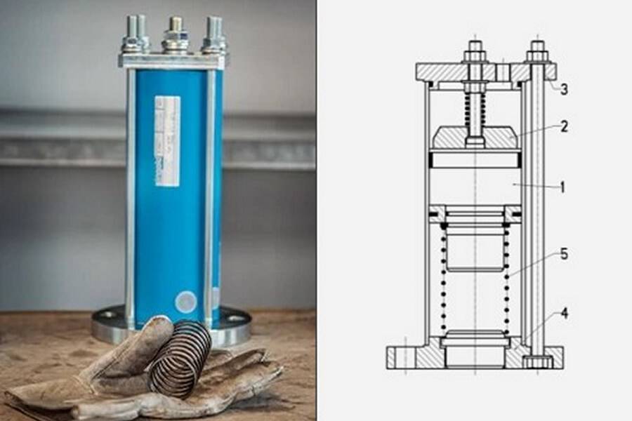
singold pneumatic knocker – Type K

Operation of pneumatic knocker at bridging and cleaning out of the silo
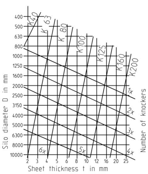
Selection Chart for Pneumatic Knockers for a 60° cone
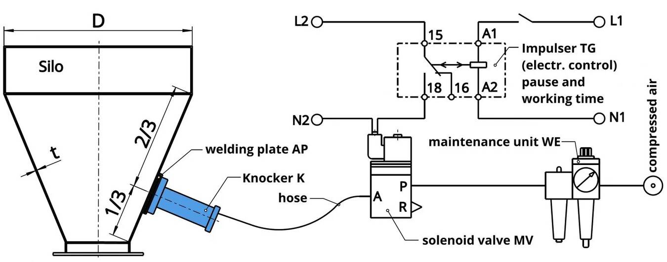
Components needed for assembly and operation of the pneumatic knocker
More information
Pneumatic knocker: configurator, available versions, etc.: https://singold.tech/en/pneumatic-knocker-type-k/ |